Part 2 - Step 1: Starting with setting up shifting UVs
To be able to display any arbitrary equally sized sector in a UV map, we need to be able to iterate over every spot in the whole thing like a 2D Array. More uniquely for simplicity’s sake I’d like to iterate over the whole array using a single index, essentially mapping a 2D array to a 1D array. This is because this setup is already gonna be complex as it is and I don’t want to have to handle keying two variables for expressions in animations. If I miss keying one, things will get weird and hard to track down.
So, unfortunately, we’re gonna have to do some math.
First thing we’ll do is set up a Mapping node between the UV Map node and the Atlas’s Image Texture node. Set it to Texture mode.
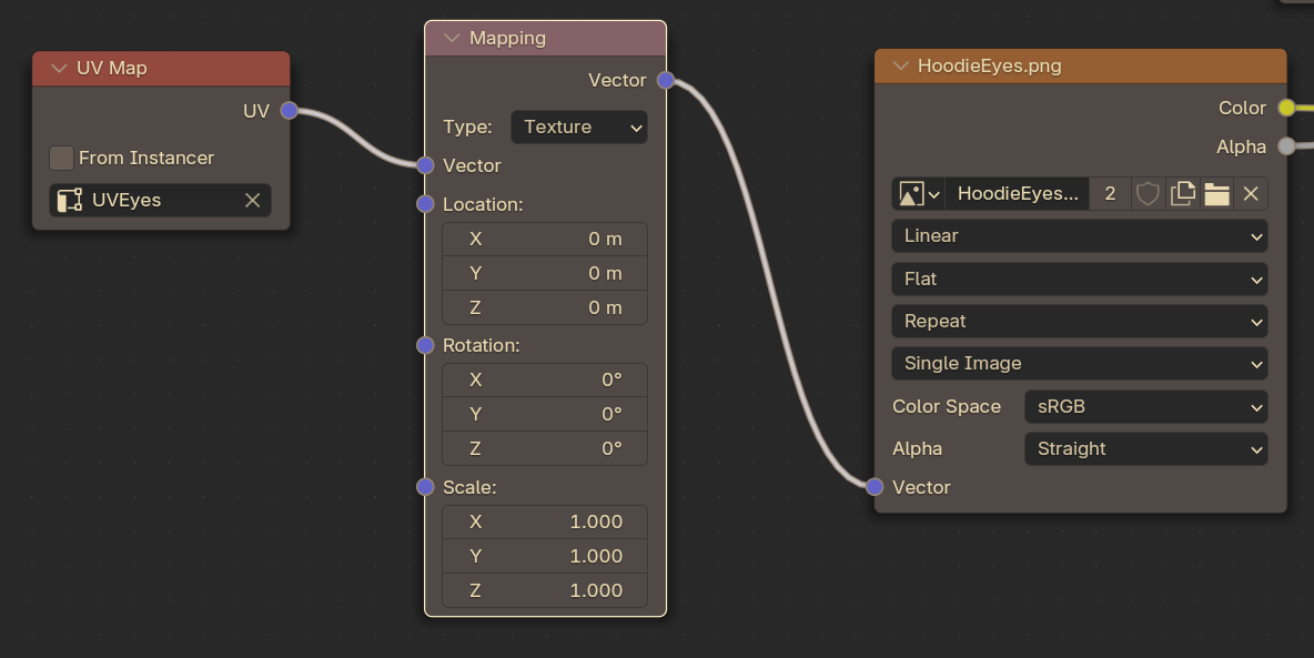
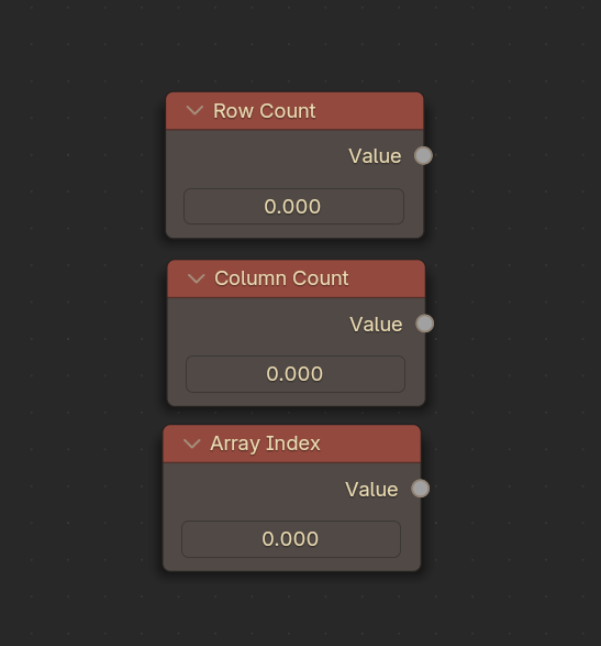
There are three main attributes that we’re going to have to have on hand. The first two are number of rows in our image, and the number of columns.
In this example image, we have 3 rows and 2 columns. So let’s set those up in their own values.
Make two Value nodes, set them as such. You can use the F2 key as a shortcut to rename them.
Next, we’re going to need to know what our current Array Index is for our array. Make another value for that, and rename it (just for clarity, nodes can get messy!)
Part 2 - Step 2: Setting up the increments.
To shift around our UVs, we essentially need to know how we can move within the space. We want our jumps to be automated, and accurate. We have two coordinates we can add to the UVs, X (left-right) and Y (up-down).
Since we have two columns, that’s two places the X coordinate can be. With 3 rows, that’s 3 places the Y coordinate can be.
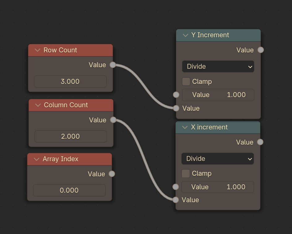
Since all coordinates exist between 0 & 1, we can figure out how much to increment by dividing 1 by the number of rows or columns!
So let’s get our X increment node and Y increment node set up by plugging the number of rows and columns into some Math nodes set to use Division:
(Hint: In the Search, look for Math nodes, not Division nodes!)
For this example, the reason I’m using 3 and 2 is because I’m going to be applying the prior techniques to this 2x3 mouth expression test atlas. All the prior steps apply, I just use the 2nd texture’s alpha as a mask and a third set of UV Coordinates.
I swapped to use this texture because a 2x2 Eye image makes the tutorial a bit harder to follow. Feel free to pick up where you left off with your own project!
Now, these two numbers dictate how far down to go each time we change an index, and how far right to go each time we change an index. In my case, each X increment is .5 (or 50%) because I have two columns (½), and the Y increment is .3333 (or 33%) because I have three rows (⅓)!
Part 2 - Step 3: Showing expressions in the 1st column.
Here’s where we start modifying our Mapping node. Drag from the Location input and search for a Combine XYZ node. We’re going to use the X and Y inputs here to shift around the UV maps.
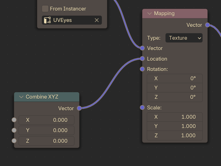
Try playing with the Combine XYZ node by itself on your own to understand how scrolling UV coordinates works!

Since we have the Y increment value, we can use a Math Node to multiply that by our current Array Index and then plug that into the Y value of the Combine XYZ node. So now, when we scroll our Current Index up and down, the UVs will move up and down as well!
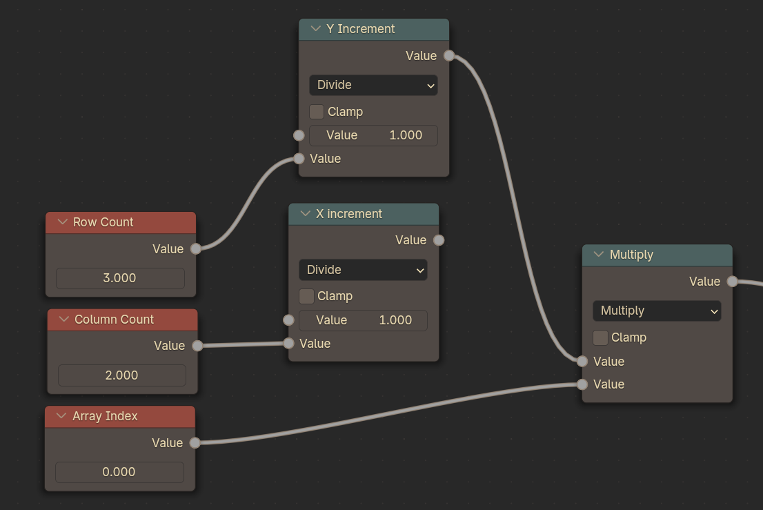
The Value node is a float, so we can’t jump to the exact accurate point YET, but this step was only to set the vertical scrolling working first. We’ll lock it down to exact Integer numbers later.
Also, if it’s not, make sure your Image Textures are set to Repeat if you changed them, this method won’t work otherwise.
Part 2 - Step 4: Modulo Madness / Expressions in the 2nd Column
Alright, here’s where the weirdest math happens.
What we need to happen in this step is for the X value of the array to step to the right when the Y values have been iterated through. When we’ve gone through the left column, step to the right column.
The first bit is to determine exactly when we’ve iterated through the first set of rows in the first column so we can move to the second column!
To determine when we have iterated through the first row, we can just count the amount of rows we’ve already iterated through. Every three, we know we need to jump right by one. To get this we can take our current Array Index (which here represents the amount of rows we’ve moved), and divide that by Row Count, and then Floor it. The end result is a number that only increments by 1 every 3 Indices, which is the amount of rows we have! We can call this ColumnIndex)
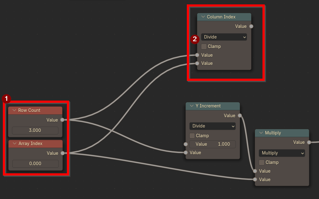
Row Count Divided by Array Index is our Column Index
We then plug this value into a Floor Math Node, before plugging THAT into a Truncated Modulo where we perform (ColumnCount % ColumnIndex). Modulo is a math operation (A % B) that gives us either 1) variable A is smaller than B or 2) The Difference of A and the closest multiple of B if A is larger than B).
(The fact that it’s Truncated here is just because there is no standard Modulo in Blender for single values. Only Truncated or Floored, and neither give EXACTLY what we want. The Floor node is used to get us the exact output we desire.)
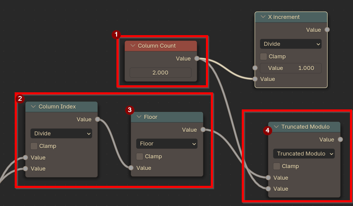
Yeah, we haven’t used our X Increment yet. Hang tight, we’re about to!
Note: If you’d like to learn why this works, click here! Otherwise, skip ahead!
Let’s take a short detour to explain that. Because that was a confusing series of sentences. Math is better with examples.
Example 1
- Let’s say A = 8, and B = 3, and we’re taking A % B.
- A is 8. The closest whole multiple of 3 to 8, is 6.
- The next multiple is 9, that’s too big. So we use 6.
- 8 - 6 = 2.
- So 8 % 3 = 2.
This means 8 mod 3 is 2!
Example 2
- Okay, what if A = 11 and B = 5?- The closest whole multiple of 5 to 11 is 10.
- The next multiple is 15, which is too big. So we use 10.
- 11 - 10 = 1
- So 11 % 5 = 1
That means 11 mod 5 is 1!
Okay, now that I’ve given you the tiniest math primer of all time, let’s look at what we’re actually doing:
The two X values we can have in our test image are Column 1 (which is X index 0) or Column 2 (which is X Index 1).
That’s because X * 0 doesn’t move our UVs, and X * 1 moves our UVs over one column. Once we do X * 2, we’ve looped and we’re back where we started, because our X Increment size is 50% and (50% * 2) is 100%.
Because of that, the only two numbers we care about getting are 0 or 1. Let’s go through our Modulo process by hand to see what happens here.
First Step
- ColumnIndex is A, and A = 0. Here, we haven’t done anything yet, so ColumnCount is B, and B = 2.
- 0 is a special case, because 0 divided by anything is 0.
- So 0 % 2 is 0.
Second Step
- When ColumnIndex is 1:
- 1 is smaller than 1, so we return A.
- 1 % 2 = 1.
Third Step
- When ColumnIndex is 2
- 2 is exactly divisible by 2, so there is no remainder.
- 2 % 2 = 0
Fourth Step
- When ColumnIndex is 3
- 3’s closest multiple of 2 is….2.
- 3 - 2 is 1.
- So 3 % 2 = 1
Fifth Step
- When ColumnIndex is 4
- 4 is exactly divisible by 2.
- So, no remainder.
- 4 % 2 is 0.
...and so on.
So if we look at this, as we increment the final horizontal result is either 0 or 1 every 3 rows we increment over. Which gives us EXACTLY the movement we need!
So now that we've gone over that, let's get back to our actual tutorial.
Use a Math Node to Multiply that output from the Modulo by the X Increment, and then plug that into the final result.
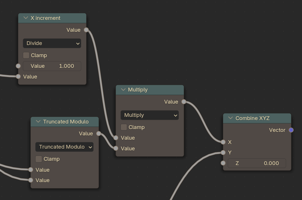
So, now when we increment our Current Index, our face will show the expressions in the atlas in order from the first column, and then the second column, and then it will repeat!
As our last step, let’s clean up all this spaghetti…
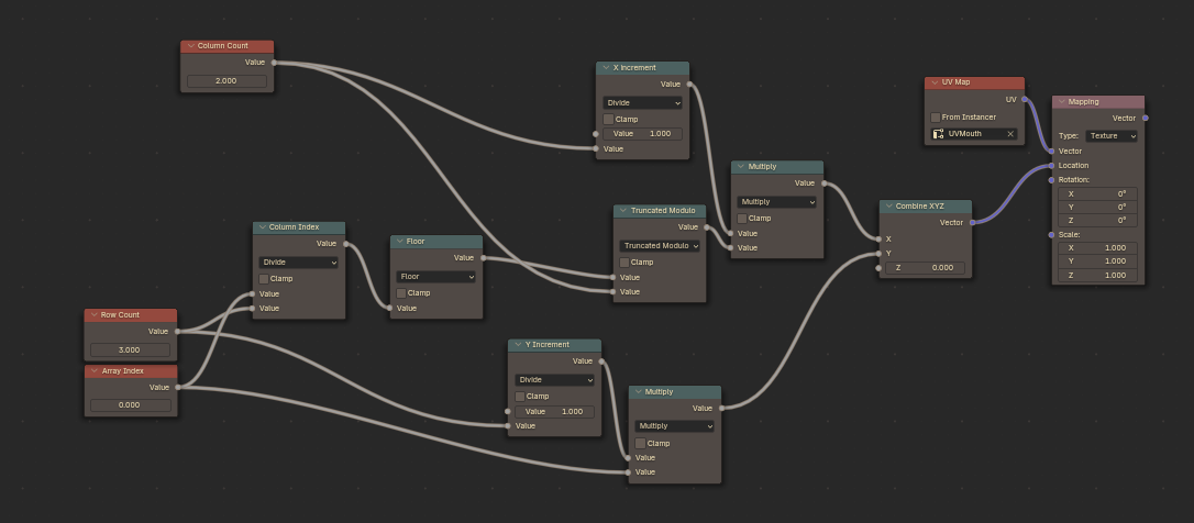
Select all of the blue Math nodes here and press CTRL+G to Group them into a single node! This will also put you into the Group view within the Material. Press N to bring up the sidebar and select the Group tab.
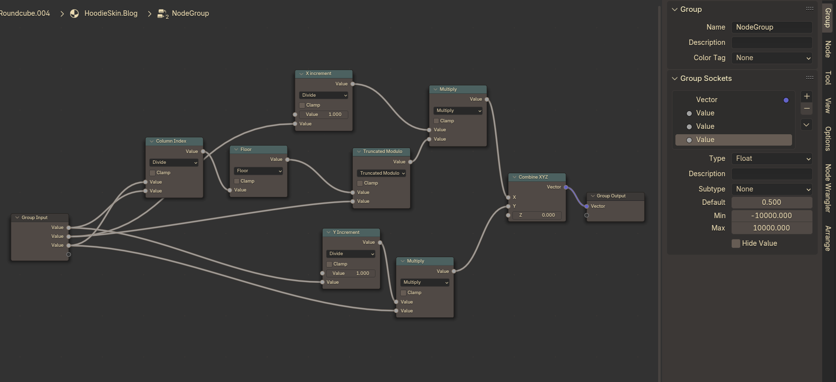
Select the Values within the Group sockets and edit them to rename your Group Inputs.
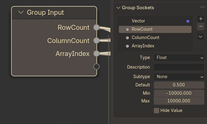
Feel free to rename the Output Vector as well, if you feel like doing so!
Press Tab to exit the Group view, then with the Group node selected, Press F2 to rename the node! You can also select the Group inside to rename that as well. Lastly, ensure you give the group a Fake User by pressing the Shield icon to ensure that garbage collection does not delete the group under any circumstance.
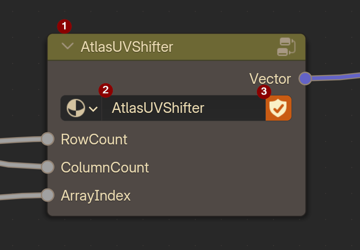
Now, you can dynamically scroll through each column as well!

Next up, we’ll be configuring how to control this using Custom Attributes and allowing them to be keyed by the Action Editor! See that article here!